Getting started
Soldering
Important
Please note that some components in this board need to be soldered.
If you have never soldered or you want to improve your soldering techniques I recommend you the Adafruit Guide To Excellent Soldering
For better understanding where is located each component on the board check out the PCB layout with the interactive BOM.
Powering
The Smart Lights X4 can be powered in two ways: through the DC Power Jack or through the AC Input, but not simultaneously.
Caution
Power the board only after making all the connections
DC Power Jack
The DC Power Jack is a very common connector for home power supplies. The size of the one by default is a 5.5mm (outer) and 2.1mm (inner) diameter.
Since there are many power supplies with this connector it is important, before plugging any power supply to the board, checking out a few important details:
The output voltage of the power supply has to be in the range of 5 to 24VDC.
The power of the power supply is enough for the LEDs you want to power.
The connector polarity is correct. Inner pole positive and outer negative

AC Input
If your preffer not to use external power suplies you can assemble one of the following ones directly on the board:
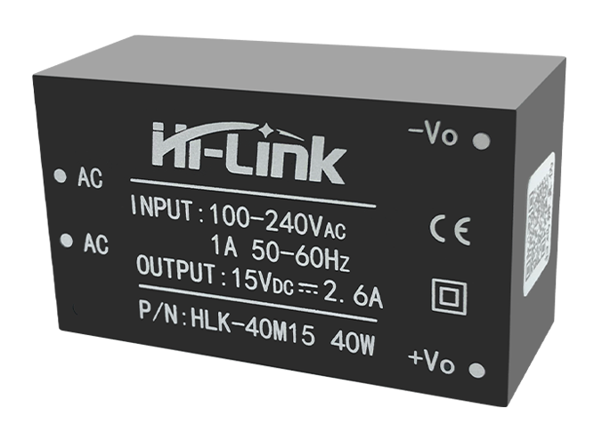
HLK-40M Series: 40W power supplies with output voltages 5/9/12/15/24VDC
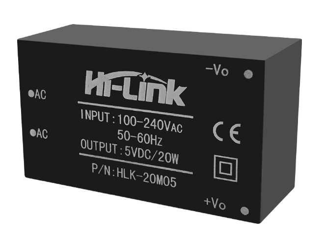
HLK-20M Series: 20W power supplies with output voltages 5/9/12/15/24VDC
Danger
If your are using the AC power never touch the board while is powered.
I/O
The Smart Lights X4 supports up to 4 independent analog outputs and 8 digital inputs/outputs:
GPIO |
Input |
Output |
Name |
|---|---|---|---|
16 |
✅ |
✅ |
Auxiliar 1 |
17 |
✅ |
✅ |
Auxiliar 2 |
18 |
✅ |
✅ |
Auxiliar 3 |
19 |
✅ |
✅ |
Auxiliar 4 |
23 |
❌ |
✅ |
Output 1 |
25 |
❌ |
✅ |
Output 2 |
26 |
❌ |
✅ |
Output 3 |
27 |
❌ |
✅ |
Output 4 |
32 |
✅ |
❌ |
Input 1 |
33 |
✅ |
❌ |
Input 2 |
34 |
✅ |
❌ |
Input 3 |
35 |
✅ |
❌ |
Input 4 |
Analog outputs:
Each one of these outputs are PWM controlled individually through power mosfets. Despite the PCB layout should allow a correct heat dissipation, an additional heatsink would be recommendable for applications where a high current is expected (long LED strips or high intensity LEDs)
The connection port of each of the outputs is located on the top left part of the board and is done through 3.5mm screw terminals. The polarity of the connection is defined on the PCB silkscreen.
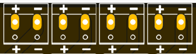
From left to right, the pin definion of each output is:
- Output 1:
GPIO23
- Output 2:
GPIO25
- Output 3:
GPIO26
- Output 4:
GPIO27
Digital inputs/outputs:
The connection port of these pins is located on the top right part of the board and is done through 2.54 pins.
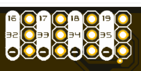
From this set of pins, there are two groups: inputs and auxiliar pins. The difference is that the input pins are pulled-down through 10k resistors and are connected on the PCB to the pushbuttons.
- Input 1:
GPIO32
- Input 2:
GPIO33
- Input 3:
GPIO34
- Input 4:
GPIO35
Hint
These pins correspond to the ADC_1 (chanels 4-7) of the ESP-32, and therefore can be used as analog inputs, always taking into account that are pulled-down already on the board.
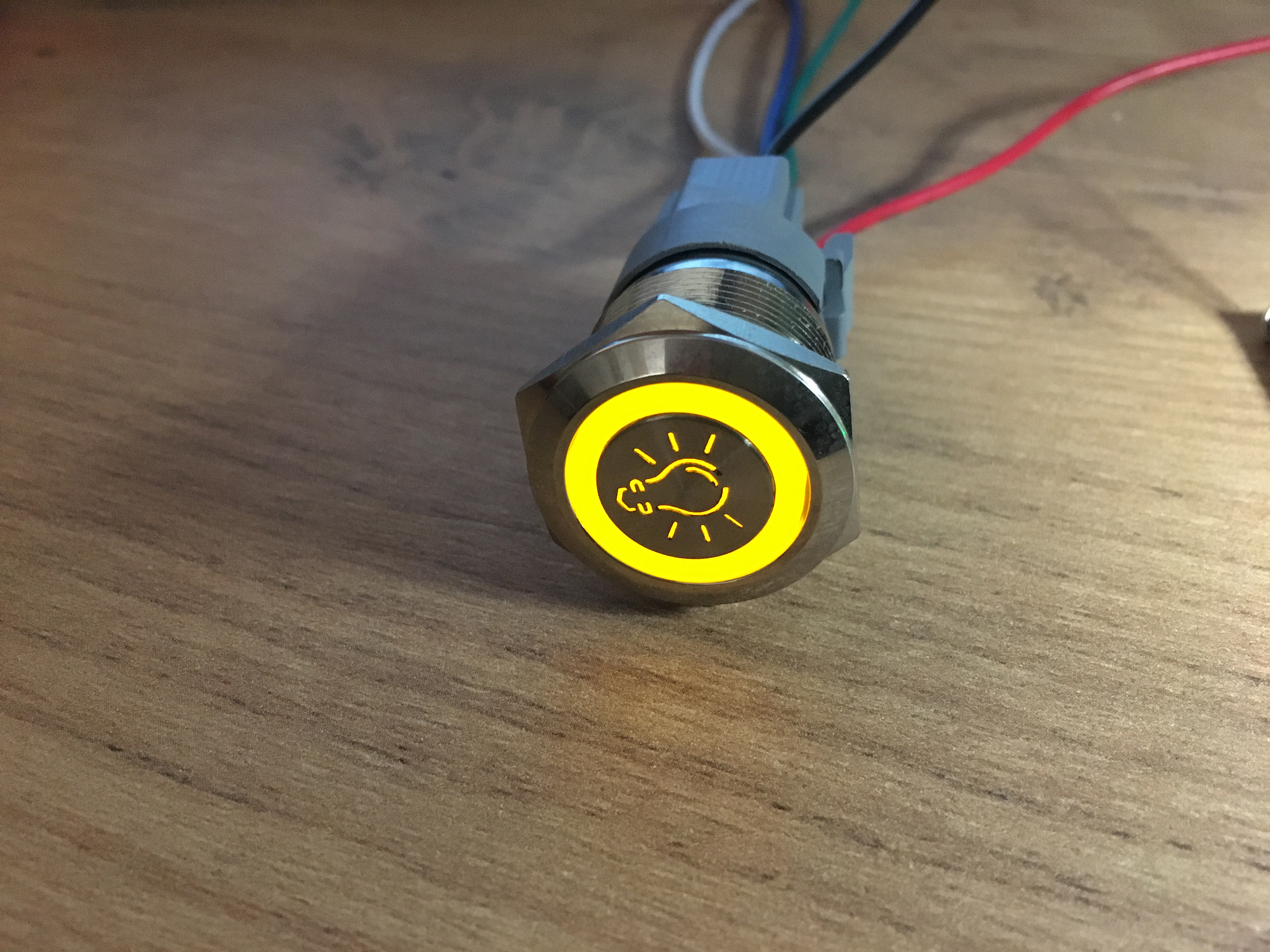
The auxiliary pins access directly to the microcontroller pins and can behave as digital input/outputs. The intention of these auxiliar pins is to control LED rings on pushbuttons that have this feature
- Auxiliar 1:
GPIO16
- Auxiliar 2:
GPIO17
- Auxiliar 3:
GPIO18
- Auxiliar 4:
GPIO19
Communications
In addition to the I/O mentioned before, there is also a direct connection to:
IIC (\(I^2C\)) bus:
- SDA:
GPIO21
- SCL:
GPIO22
Serial bus:
- Tx:
GPIO1
- Rx:
GPIO3
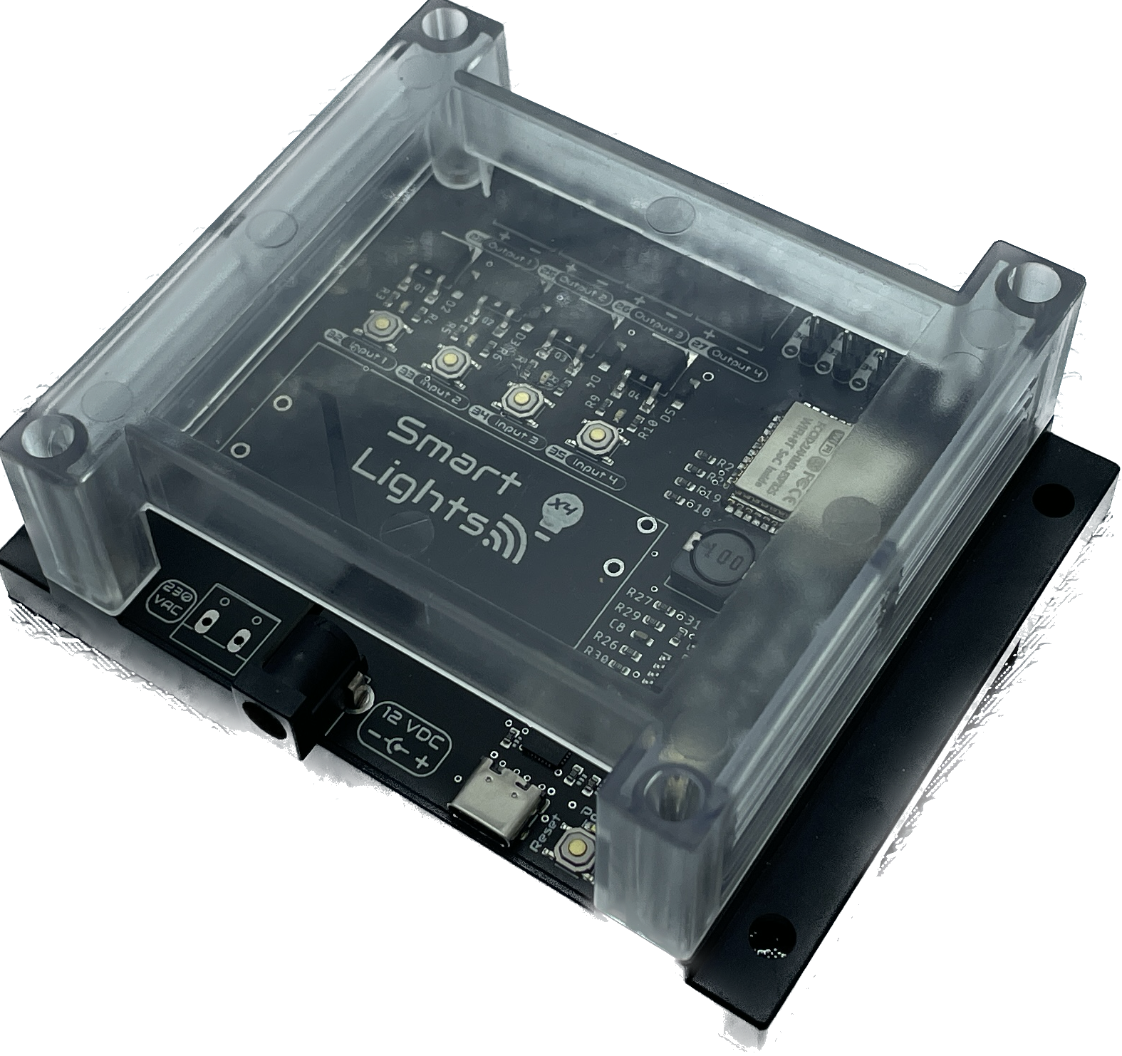
Enclosure
The Smart Lights X4 has been designed to fit in the electronics enclosure LK-PLC01, compatible with DIN rails and screws, and it is recommended for indoors only.
- External size:
115x90x40mm
- Material:
ABS Plastic
- Color:
Transparent cover, black or beige base