Getting started
Soldering
Important
Please note that some components in this board need to be soldered.
If you have never soldered or you want to improve your soldering techniques I recommend you the Adafruit Guide To Excellent Soldering
For better understanding where is located each component on the board check out the PCB layout with the interactive BOM.
Powering
The Smart Lights X1 can be powered in two ways: through the DC Power Jack or through the Serial port, but it is not recommended to be done simultaneously if you don’t know exactly how the internal powering routes are set.
Caution
Power the board only after making all the connections
DC Power Jack
The DC Power Jack is a very common connector for home power supplies. The size of the one by default is a 5.5mm (outer) and 2.1mm (inner) diameter.
Since there are many power supplies with this connector it is important, before plugging any power supply to the board, checking out a few important details:
The output voltage of the power supply has to be in the range of 5 to 24VDC.
The power of the power supply is enough for the LEDs you want to power.
The connector polarity is correct. Inner pole positive and outer negative

Serial port
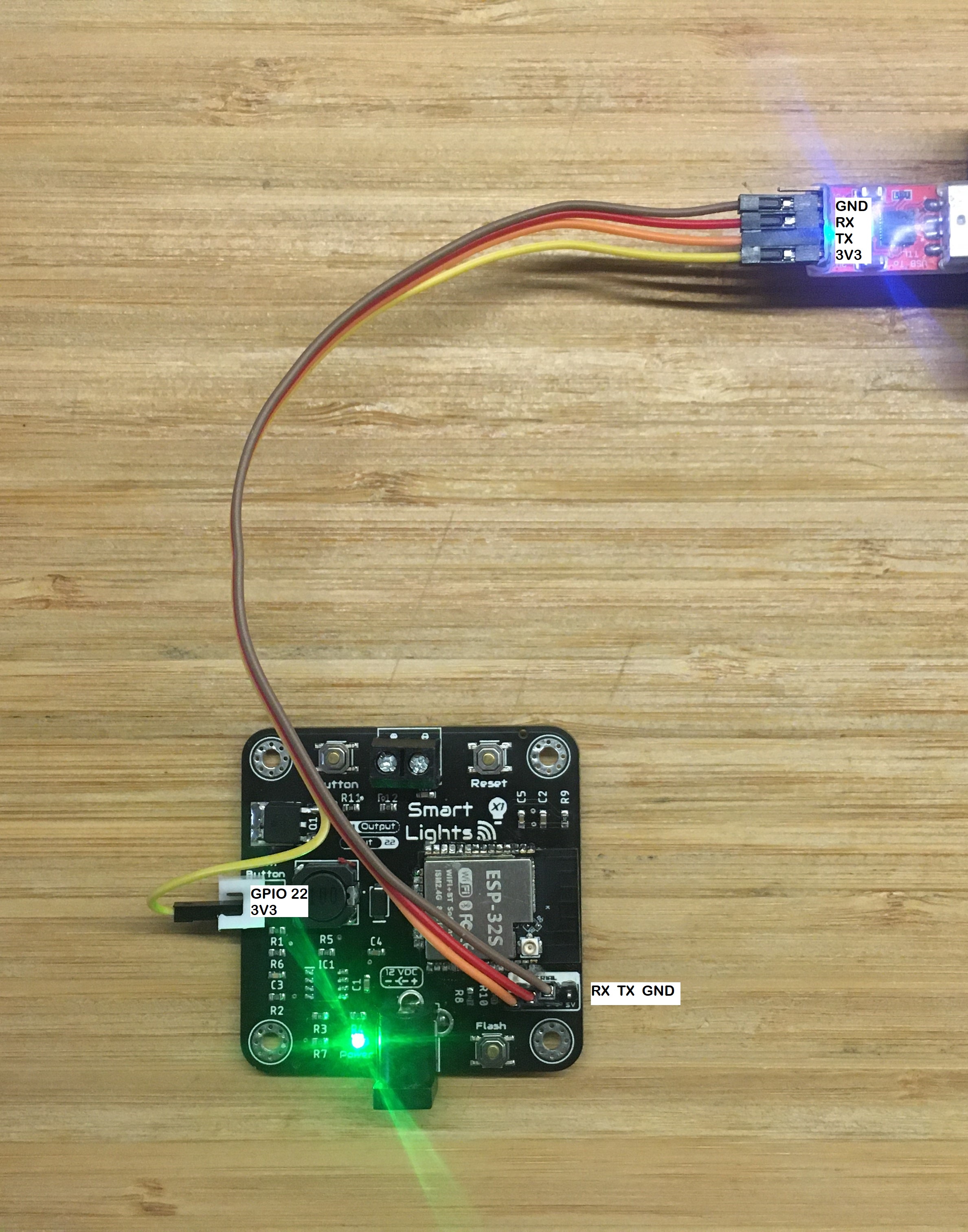
Despite the normal usage of the board will be usually done through the DC Jack, whenever you need to programm the board manually, it is recommendable to power it through the Serial port. However on the Smart Lights X1, the power regulator accepts a minimum voltage of 5V, which makes it unsuitable to bring down to 3.3V the 5V input voltage at Serial port.
Therefore, it is recommendable to make a connection as the figure whenever you want to programm your Smart Lights X1 with an external USB-to-TTL programmer.
I/O
The Smart Lights X1 has the capability of reading 1 Input and controlling 1 output. :Input: GPIO22 :Output: GPIO21
The input port is located on the left side, a 2.54 pitched connector that could be directly plugged to a pushbutton.
Note
The input pin is already pulled-down, through a 10k resistor, and connected on the PCB to the pushbuttons.
The output, located on the upper part of the board through a 3.5mm screw terminal, is PWM controlled through the power mosfet. Despite the PCB layout should allow a correct heat dissipation, an additional heatsink would be recommendable for applications where a high current is expected (long LED strips or high intensity LEDs)
Communications
In addition to the I/O mentioned before, there is also a direct connection to:
Serial bus:
- Tx:
GPIO1
- Rx:
GPIO3
Enclosure
The Smart Lights X1 PCB can be mounted in a custom 3D printable enclosure that you can print on your own 3D printer.